Usage of the GUI
The GUI application is presented in Fig. 4.
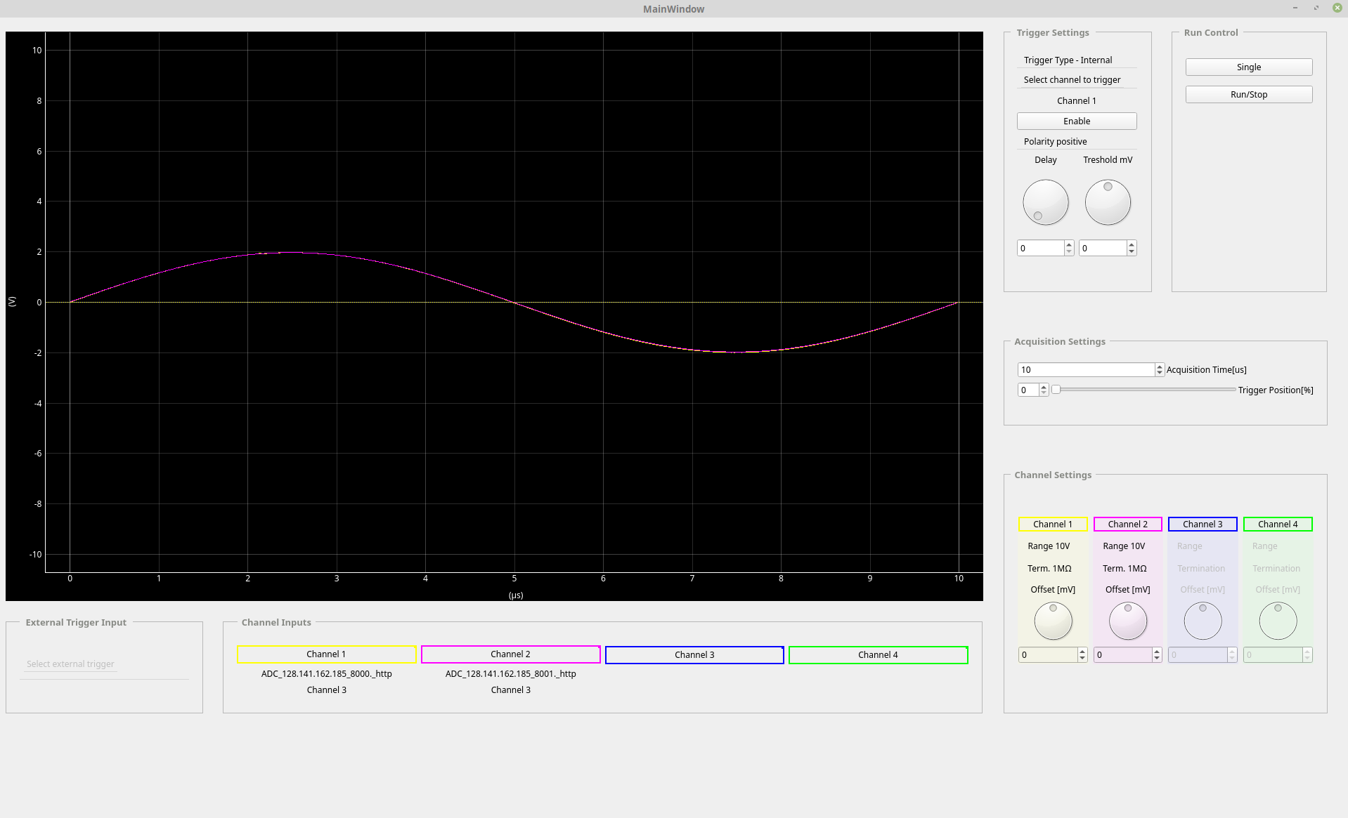
Fig. 4 Screenshot of the GUI application
Channels selection
Just like in standard oscilloscope, there is a possibility of observing up to 4 channels. Any channel of any available ADC can be connected to the particular channel of the GUI.
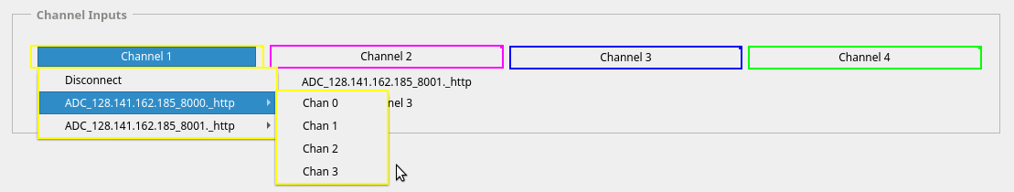
Fig. 5 Selection of GUI channels
Triggers selection
The ADCs could be triggered either by external trigger pulse or when the signal of the observed channel crosses the threshold value (internal trigger).
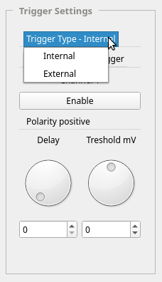
Fig. 6 Selection of trigger type
Internal trigger
If the internal trigger is selected, the GUI could be triggered on any channel to which a signal is connected.
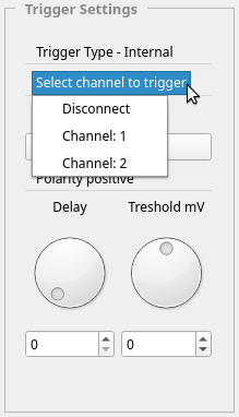
Fig. 7 Selection of internal trigger
External trigger
If the external trigger is selected, the GUI could be triggered by the external trigger input of any connected ADC.
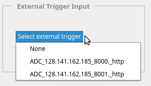
Fig. 8 Selection of external trigger
Channels settings
Currently available channels settings are the following:
- range
- termination
- offset
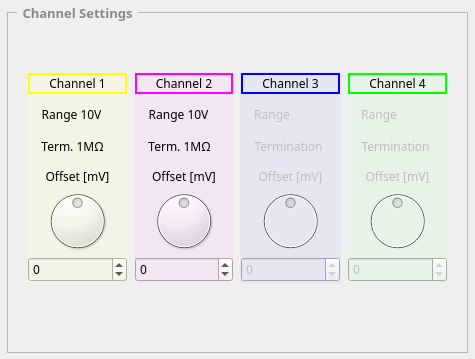
Fig. 9 Channels settings
Trigger settings
Currently available trigger settings are the following:
- polarity
- delay
- threshold (in case of internal trigger)
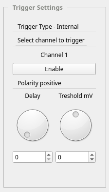
Fig. 10 Trigger settings
Run control
There are two available modes:
- single acquisition
- continuous acquisition
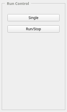
Fig. 11 Run control
Acquisition settings
Acquisition settings allow modifying the acquisition time and position of the trigger. Position of the trigger is given in percentage of the acquisition time.
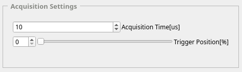
Fig. 12 Acquisition settings